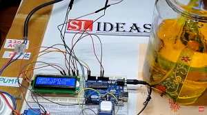
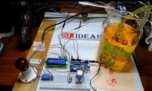
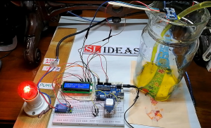
Automatic Water Level Controller
Automatic Water Level Controller
An automatic water level controller is a device that automatically controls the water level in a tank or reservoir. It is an essential device in modern households, industries, and agriculture to conserve water and ensure optimal water usage. With the increasing demand for water conservation, it has become necessary to use advanced water management systems that can efficiently control the water levels in storage tanks. One such device is the automatic water level controller using Arduino.
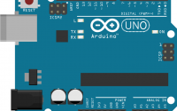
The Arduino board is an open-source microcontroller platform that is widely used for a variety of electronics projects. It is an ideal platform for developing a water level controller due to its versatility, ease of use, and low cost. In this blog post, we will explore how to build an automatic water level controller using the Arduino microcontroller and some common sensors.
Components Required
The following components are required to build an automatic water level controller using Arduino:
- Arduino Uno Board
- Ultrasonic sensor
- Relay module
- Resistors
- Transistor
- LED
- Jumper Wires
Working Principle
The automatic water level controller works by measuring the water level in the tank and triggering a relay to turn the water pump on or off as required. The ultrasonic sensor is used to measure the water level in the tank. The sensor sends a pulse of high-frequency sound that reflects off the water surface and is received back by the sensor. The time taken for the sound to travel to the water’s surface and back is used to calculate the water level.
The relay module is used to turn the water pump on or off. When the water level in the tank drops below a certain threshold, the relay module is triggered, and the water pump is turned on. When the water level in the tank reaches the maximum level, the relay module is turned off, and the water pump is turned off.
The transistor is used as a switch to control the flow of current in the relay module. The LED is used to indicate the status of the water pump. If the water pump is turned on, the LED will be lit. If the water pump is turned off, the LED will be turned off.
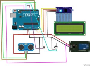
Circuit Diagram
The circuit diagram for the automatic water level controller using Arduino is shown below:
Code
The following code is used to control the water level in the tank using the Arduino board:
#include <EEPROM.h>

#include <Wire.h>
#include <LiquidCrystal_I2C.h>


LiquidCrystal_I2C lcd(0x27, 16, 2);


long duration, inches;
int set_val,percentage;
bool state,pump;


void setup() {

lcd.begin();
lcd.print("WATER LEVEL:");
lcd.setCursor(0, 1);
lcd.print("PUMP:OFF MANUAL");

pinMode(2, OUTPUT);
pinMode(3, INPUT);
pinMode(10, INPUT_PULLUP);
pinMode(11, INPUT_PULLUP);
pinMode(13, OUTPUT);

set_val=EEPROM.read(0);
if(set_val>150)set_val=150;
}
void loop() {

digitalWrite(2, HIGH);
delayMicroseconds(10);
digitalWrite(2, LOW);
duration = pulseIn(3, HIGH);
inches = microsecondsToInches(duration);

percentage=(set_val-inches)*100/set_val;

lcd.setCursor(12, 0);
if(percentage<0)percentage=0;
lcd.print(percentage);
lcd.print("% ");

if(percentage<30&digitalRead(11))pump=1;
if(percentage>99)pump=0;
digitalWrite(13,!pump);

lcd.setCursor(5, 1);
if(pump==1)lcd.print("ON ");
else if(pump==0) lcd.print("OFF");

lcd.setCursor(9, 1);
if(!digitalRead(11))lcd.print("MANUAL");
else lcd.print("AUTO ");

if(!digitalRead(10)&!state&digitalRead(11)){
state=1;
set_val=inches;
EEPROM.write(0, set_val);
}

if(!digitalRead(10)&!state&!digitalRead(11)){
state=1;
pump=!pump;

}

if(digitalRead(10))state=0;


delay(500);
}
long microsecondsToInches(long microseconds) {
return microseconds / 74 / 2;
}
I2C LCD Display Library :

