Keypad Door Lock Using Arduino
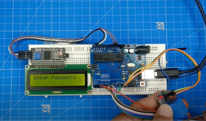
An electronic door lock system is a convenient and secure way to control access to your home or office. It eliminates the need for traditional keys and makes it easier to manage who has access to your space. In this blog, we will explore how to build an electronic door lock system using the Arduino Uno microcontroller, an LCD I2C display, a 4×4 keypad, and a 12V solenoid door lock.
Materials required for this project are:
Step 1: Connect the LCD I2C display to the Arduino Uno
The first step in building the electronic door lock system is to connect the LCD I2C display to the Arduino Uno. This is done by connecting the SDA and SCL pins of the LCD to the A4 and A5 pins of the Arduino, respectively.
Step 2: Connect the Keypad to the Arduino Uno
The next step is to connect the 4×4 keypad to the Arduino. The keypad has 8 pins, which are connected to the digital pins of the Arduino. The connections can be made as follows:
- Row 1 (pin 1) to digital pin 2
- Row 2 (pin 2) to digital pin 3
- Row 3 (pin 3) to digital pin 4
- Row 4 (pin 4) to digital pin 5
- Column 1 (pin 5) to digital pin 6
- Column 2 (pin 6) to digital pin 7
- Column 3 (pin 7) to digital pin 8
- Column 4 (pin 8) to digital pin 9
Step 3: Connect the Solenoid Door Lock to the Arduino Uno
The 12V solenoid door lock is connected to the Arduino by connecting the positive and negative terminals to the digital pins 10 and 11, respectively.
Step 4: Upload the code to the Arduino
Keypad Door Lock Using Arduino – Code
#include <Keypad.h>
#include<EEPROM.h>
#include <Wire.h>
#include <LiquidCrystal_I2C.h>

LiquidCrystal_I2C lcd(0x27, 16, 2);
char password[4];
char initial_password[4],new_password[4];
int vcc=11;
int i=0;
int relay_pin = 11;
char key_pressed=0;
const byte rows = 4;
const byte columns = 4;
char hexaKeys[rows][columns] = {
{'1','2','3','A'},
{'4','5','6','B'},
{'7','8','9','C'},
{'*','0','#','D'}
};
byte row_pins[rows]={2,3,4,5};
byte column_pins[columns]={6,7,8,9};
Keypad keypad_key=Keypad( makeKeymap(hexaKeys),row_pins,column_pins,rows,columns);

void setup(){
lcd.begin();
lcd.backlight();
pinMode(relay_pin, OUTPUT);
pinMode(vcc, OUTPUT);


lcd.print(" MOUNT DYNAMICS ");
lcd.setCursor(0,1);
lcd.print("Electronic Lock ");
delay(3000);
lcd.clear();
lcd.print("Enter Password");
lcd.setCursor(0,1);
initialpassword();
}
void loop(){
digitalWrite(relay_pin,HIGH);

key_pressed = keypad_key.getKey();
if(key_pressed=='#')
change();
if (key_pressed)
{
password[i++]=key_pressed;
lcd.print(key_pressed);
}
if(i==4)
{
delay(200);
for(int j=0;j<4;j++)
initial_password[j]=EEPROM.read(j);
if(!(strncmp(password, initial_password,4))){
lcd.clear();
lcd.print("Pass Accepted");
digitalWrite(relay_pin,LOW);
delay(2000);
lcd.setCursor(0,0);
lcd.print("Pres >START< to");
lcd.setCursor(0,1);
lcd.print("change the pass");
delay(3000);
lcd.clear();
lcd.print("Enter Password:");
lcd.setCursor(0,1);
i=0;
}
else{
digitalWrite(relay_pin, HIGH);
lcd.clear();
lcd.print("Wrong Password");
lcd.setCursor(0,0);
lcd.print("Pres >#< to");
lcd.setCursor(0,1);
lcd.print("change the pass");
delay(2000);
lcd.clear();
lcd.print("Enter Password");
lcd.setCursor(0,1);
i=0;
}}}


void change(){
int j=0;
lcd.clear();
lcd.print("Current Password");
lcd.setCursor(0,1);
while(j<4){
char key=keypad_key.getKey();
if(key)
{
new_password[j++]=key;
lcd.print(key);
}
key=0;}
delay(500);

if((strncmp(new_password, initial_password, 4))){
lcd.clear();
lcd.print("Wrong Password");
lcd.setCursor(0,1);
lcd.print("Try Again");
delay(1000);}

else{
j=0;
lcd.clear();
lcd.print("New Password:");
lcd.setCursor(0,1);

while(j<4){
char key=keypad_key.getKey();
if(key)
{
initial_password[j]=key;
lcd.print(key);
EEPROM.write(j,key);
j++;}}
lcd.print("Pass Changed");
delay(1000);}

lcd.clear();
lcd.print("Enter Password");
lcd.setCursor(0,1);
key_pressed=0;
}

void initialpassword(){
int j;
for(j=0;j<4;j++)
EEPROM.write(j,j+49);
for(j=0;j<4;j++)
initial_password[j]=EEPROM.read(j);}
The final step is to upload the code to Arduino. The code will take input from the keypad, display it on the LCD, and check if it matches the pre-programmed password. If the password is correct, the solenoid door lock will be activated, allowing access. If the password is incorrect, access will be denied.
In conclusion, the electronic door lock system using the Arduino Uno, LCD I2C display, 4×4 keypad, and 12V solenoid door lock is a simple and cost-effective way to control access to your home or office. With this project, you will gain hands-on experience in using the Arduino, LCD I2C display, keypad, and solenoid door lock, and you will have a functional electronic door lock system that you can use for your own purposes.

Top 5 DIY Electronics Projects for Engineering Students

Smart home automation