Line Follower Robot
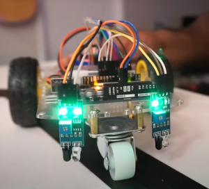
Line follower robots have been around for many years and have become a popular DIY project for hobbyists and students alike. These robots are designed to follow a specific path, typically marked by a black line on a white background, and are used in various applications such as industrial automation, educational projects, and scientific research. In this blog post, we will discuss the basics of line follower robots, their components, and how to build one from scratch.
What is a Line Follower Robot?
A line follower robot is a type of mobile robot that is designed to follow a path defined by a line. It uses sensors to detect the line and control its movements accordingly. The line can be marked with any contrasting color, such as black on white or white on black, and can be of any width. The robot’s primary function is to follow the line as accurately as possible while avoiding obstacles or deviations from the path.
Components of a Line Follower Robot
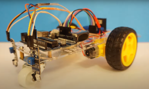
The components of a line follower robot include a microcontroller, sensors, motor driver, and motors. The microcontroller acts as the brain of the robot, processing sensor data and controlling the movements of the motors. Sensors, typically infrared or photo-reflective, detect the line and provide data to the microcontroller. The motor driver is used to control the speed and direction of the motors, and the motors are used to move the robot.
Building a Line Follower Robot
Building a line follower robot from scratch can seem like a daunting task, but with the right instructions and components, it is a fairly straightforward process. Here are the steps to building your own line follower robot:
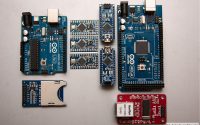
- Choose a Microcontroller: The microcontroller is the brain of the robot and is responsible for processing sensor data and controlling the motors. The most commonly used microcontroller for line follower robots is the Arduino Uno.
- Choose Sensors: There are several types of sensors that can be used for line-following robots, including infrared, photo-reflective, and laser. Infrared and photo-reflective sensors are the most common and are both easy to use and reliable.
- Choose a Motor Driver: The motor driver is responsible for controlling the speed and direction of the motors. There are several options available, including L298N and TB6612FNG.
- Choose Motors: The motors are responsible for moving the robot and can be DC motors or stepper motors. DC motors are the most commonly used for line follower robots, as they are simple to control and have high torque.
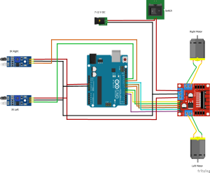
- Assemble the Robot: Once you have all of your components, it is time to assemble the robot. Start by connecting the sensors and motor driver to the microcontroller. Then, connect the motors and any additional components, such as power supplies and batteries.
- Write the Code: The code for a line follower robot is relatively simple and can be written using the Arduino programming language. The code should include instructions for processing sensor data, controlling the motors, and making the robot follow the line.
- Test the Robot: Once the robot is assembled and the code is written, it is time to test the robot. Start by testing each component individually, and then test the entire system to ensure that it is working correctly.
Circuit Diagram – Line Follower Robot
Arduino Code – Line Follower Robot
#define IR_SENSOR_RIGHT 11
#define IR_SENSOR_LEFT 12
#define MOTOR_SPEED 180

//Right motor
int enableRightMotor=6;
int rightMotorPin1=7;
int rightMotorPin2=8;

//Left motor
int enableLeftMotor=5;
int leftMotorPin1=9;
int leftMotorPin2=10;

void setup()
{
//The problem with TT gear motors is that, at very low pwm value it does not even rotate.
//If we increase the PWM value then it rotates faster and our robot is not controlled in that speed and goes out of line.
//For that we need to increase the frequency of analogWrite.
//Below line is important to change the frequency of PWM signal on pin D5 and D6
//Because of this, motor runs in controlled manner (lower speed) at high PWM value.
//This sets frequecny as 7812.5 hz.
TCCR0B = TCCR0B & B11111000 | B00000010 ;

// put your setup code here, to run once:
pinMode(enableRightMotor, OUTPUT);
pinMode(rightMotorPin1, OUTPUT);
pinMode(rightMotorPin2, OUTPUT);

pinMode(enableLeftMotor, OUTPUT);
pinMode(leftMotorPin1, OUTPUT);
pinMode(leftMotorPin2, OUTPUT);

pinMode(IR_SENSOR_RIGHT, INPUT);
pinMode(IR_SENSOR_LEFT, INPUT);
rotateMotor(0,0);
}


void loop()
{

int rightIRSensorValue = digitalRead(IR_SENSOR_RIGHT);
int leftIRSensorValue = digitalRead(IR_SENSOR_LEFT);

//If none of the sensors detects black line, then go straight
if (rightIRSensorValue == LOW && leftIRSensorValue == LOW)
{
rotateMotor(MOTOR_SPEED, MOTOR_SPEED);
}
//If right sensor detects black line, then turn right
else if (rightIRSensorValue == HIGH && leftIRSensorValue == LOW )
{
rotateMotor(-MOTOR_SPEED, MOTOR_SPEED);
}
//If left sensor detects black line, then turn left
else if (rightIRSensorValue == LOW && leftIRSensorValue == HIGH )
{
rotateMotor(MOTOR_SPEED, -MOTOR_SPEED);
}
//If both the sensors detect black line, then stop
else
{
rotateMotor(0, 0);
}
}


void rotateMotor(int rightMotorSpeed, int leftMotorSpeed)
{

if (rightMotorSpeed < 0)
{
digitalWrite(rightMotorPin1,LOW);
digitalWrite(rightMotorPin2,HIGH);
}
else if (rightMotorSpeed > 0)
{
digitalWrite(rightMotorPin1,HIGH);
digitalWrite(rightMotorPin2,LOW);
}
else
{
digitalWrite(rightMotorPin1,LOW);
digitalWrite(rightMotorPin2,LOW);
}

if (leftMotorSpeed < 0)
{
digitalWrite(leftMotorPin1,LOW);
digitalWrite(leftMotorPin2,HIGH);
}
else if (leftMotorSpeed > 0)
{
digitalWrite(leftMotorPin1,HIGH);
digitalWrite(leftMotorPin2,LOW);
}
else
{
digitalWrite(leftMotorPin1,LOW);
digitalWrite(leftMotorPin2,LOW);
}
analogWrite(enableRightMotor, abs(rightMotorSpeed));
analogWrite(enableLeftMotor, abs(leftMotorSpeed));
}

